
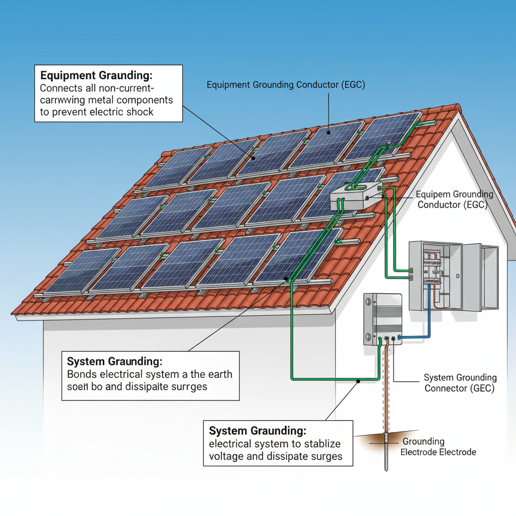
Solar grounding turned my first DIY system into a failed inspection nightmare. I thought grounding was grounding-turns out there are two completely different types, and mixing them up is like using a screwdriver as a hammer. It might work until it spectacularly doesn’t.
Here’s what I wish someone had told me: solar grounding isn’t optional, it’s not complicated, but it is absolutely critical for safety and code compliance. Miss this, and you’re looking at failed inspections, insurance headaches, and potentially dangerous electrical situations.
Equipment Grounding vs System Grounding: The Difference That Matters
Let’s clear up the confusion right off the bat. There are two types of grounding in solar systems, and they serve completely different purposes.
Equipment grounding protects you from electrocution. It’s the safety net that ensures if something goes wrong with your equipment, the electricity has a safe path to ground instead of through your body.
System grounding is about electrical reference and code compliance. It establishes a common electrical reference point for your DC system and satisfies NEC requirements.
I learned this the hard way when my inspector pointed out that my beautifully installed panels were missing proper equipment grounding. All that work, and I had to start over because I confused the two.
Equipment Grounding: Your Life Insurance Policy
Equipment grounding connects all the metal parts of your solar system that shouldn’t normally carry electricity. Panel frames, mounting hardware, combiner boxes, inverters-everything metal gets connected to ground.
This creates a low-resistance path to earth. If a hot wire touches a panel frame, instead of energizing the entire rack and waiting for you to touch it, the current flows safely to ground and trips your breaker.
Here’s what needs to be grounded:
- Solar panel frames (every single one)
- Mounting rails and hardware
- Metal conduit and junction boxes
- Inverter chassis
- Any metal enclosures
The grounding conductor needs to be sized according to NEC Table 250.122. For most residential solar systems, that’s typically 12 AWG copper minimum. Don’t cheap out here-this is literally your safety wire.
The Equipment Grounding Electrode Conductor
This fancy name just means the wire that connects your solar equipment grounding system to your home’s main electrical panel grounding system. It’s usually 6 AWG copper minimum for residential installations.
This conductor ties your solar system’s safety ground to your home’s electrical system ground. One unified grounding system, no floating metal parts waiting to bite you.
System Grounding: Meeting the Code
While equipment grounding protects people, solar grounding on the system side is about electrical reference and code compliance. The NEC requires most DC systems over 50 volts to be grounded.
System grounding means connecting one conductor of your DC system (usually the negative) to ground. This establishes a reference point and limits voltage to ground on the ungrounded conductors.
Here’s where it gets tricky: how you ground your system depends on your inverter type.
String Inverters and System Grounding
Most string inverters handle system grounding internally. The inverter connects the DC negative to ground inside the unit. You don’t need to do anything extra on the DC side-the inverter takes care of it.
Just make sure your inverter is listed for the grounding method you’re using. Some inverters are listed for positive grounding, some for negative, some for both. Read the manual.
Micro-Inverters and Power Optimizers
Micro-inverters and DC optimizers typically don’t require DC system grounding because they’re considered AC systems from an electrical code perspective. The DC system is effectively “inside” the micro-inverter.
But you still need equipment grounding. Don’t confuse system grounding requirements with equipment grounding requirements. Safety grounding is always required.
Common Solar Grounding Mistakes (Learn From My Pain)
Mistake #1: Mixing up equipment and system grounding. I’ve seen DIYers connect DC negative to equipment ground, creating a ground fault condition. Don’t do this.
Mistake #2: Inadequate wire sizing. Using 14 AWG for equipment grounding because “it’s just ground.” Wrong. Size your grounding conductors per NEC requirements.
Mistake #3: Poor connections. Grounding is only as good as your connections. Use listed grounding lugs, torque to specifications, and use anti-corrosion compound on dissimilar metals.
Mistake #4: Forgetting about voltage drop. Long grounding conductor runs still have resistance. Size accordingly or use multiple parallel paths.
The Grounding Hardware You Actually Need
Skip the cheap hardware store stuff. Solar grounding requires UL-listed components designed for outdoor use and dissimilar metal contact.
For equipment grounding:
- Grounding lugs (UL 467 listed)
- Equipment grounding conductor (bare copper or THWN green)
- Anti-corrosion compound
- Stainless steel hardware
For panel grounding: Many panels come with integrated grounding points. Use them. If not, you’ll need grounding clips that bite through the panel frame anodization to make solid electrical contact.
Don’t forget about combiner boxes and other electrical enclosures-they need grounding connections too.
Lightning Protection: What Grounding Can’t Do
Here’s a reality check: proper solar grounding won’t turn your system into a lightning rod, but it also won’t protect you from a direct lightning strike.
Lightning protection is a separate system with air terminals, down conductors, and specialized grounding electrodes. Most residential solar installations don’t include lightning protection-it’s expensive and rarely required by code.
What grounding does protect against is induced voltages from nearby lightning strikes and general electrical faults in your system.
Installation Tips That Actually Work
Start your grounding plan before you install anything. Map out where your grounding conductors will run, how you’ll connect to existing grounding electrodes, and what hardware you need.
Use continuous conductors where possible. Every splice is a potential failure point. If you must splice, use listed compression connectors and protect them from moisture.
Label everything. Your future self (and the inspector) will thank you. Mark your grounding conductors, note wire sizes, and document your grounding electrode connections.
Test your work. Use a multimeter to verify continuity between all grounded components and your main panel ground. Resistance should be near zero ohms.
Working With Inspectors
Most electrical inspectors know AC systems inside and out, but solar DC grounding can trip them up too. Come prepared with code references and manufacturer specifications.
NEC Article 690 covers solar installations. Section 690.43 specifically addresses equipment grounding, and 690.41 covers system grounding. Know these sections.
If you’ve done your panel sizing and wire gauge calculations correctly, grounding is just one more box to check for a smooth inspection.
The Bottom Line on Solar Grounding
Grounding isn’t glamorous, but it’s not optional. Equipment grounding protects lives, system grounding satisfies code requirements, and both are required for a legal, safe installation.
Don’t overthink it, but don’t skip it either. Use proper materials, follow NEC guidelines, and when in doubt, consult a qualified electrician. Your safety and your inspection depend on getting this right.
The good news? Once you understand the difference between equipment and system grounding, the rest is just following the rules and using the right hardware. Not rocket science-just careful, methodical work that keeps everyone safe.
Related Reading
For related tips, check out our fusing and protection guide. For grounding and bonding code requirements, see the National Electrical Code (NFPA 70) reference.