Solar Wire Gauge: Stop Melting Your Investment
Here’s a mistake I made so you don’t have to. I used 14 AWG wire on a run carrying 30 amps. The wire got hot enough to soften the insulation. The smell alone was educational. If you want to build a solar system that doesn’t become a cautionary tale, understanding solar wire gauge is non-negotiable — and honestly, it’s not that hard once someone explains it without the condescension.
This post covers the math, the shortcuts, and the real-world decisions you’ll face when wiring a DC solar system. No engineering degree required. I promise.
Why Solar Wire Gauge Actually Matters
Wire isn’t just a conductor. It’s also a resistor. Every foot of wire resists current flow slightly, which generates heat. The thinner the wire, the more resistance, the more heat.
In AC household circuits, that’s annoying. In a DC solar system running high amperage at low voltage, it can be genuinely dangerous. We’re talking melted insulation, tripped fuses, ruined components — or in worst cases, fires.
Here’s the kicker: voltage drop and heat are two separate problems that both trace back to undersized wire. You can have wire that doesn’t burst into flames but still bleeds so much voltage that your system performs terribly. We’ve got a full breakdown of that second problem in our guide on DIY Solar Voltage Drop: Calculate Wire Runs That Work. Read that after this one.
For now, let’s focus on not melting anything.
The Basic Rule: Amps Determine Wire Size
Here’s the core concept. Wire gauge is selected based on how many amps it needs to carry continuously — not watts, not volts. Amps.
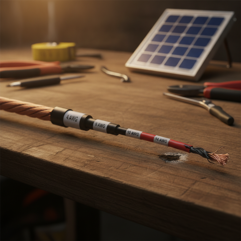
The NEC (National Electrical Code) publishes ampacity tables. These are the numbers that tell you how many amps a given wire size can safely carry without overheating. Here are the most relevant sizes for solar DIY:
- 14 AWG — 15 amps max (continuous)
- 12 AWG — 20 amps max
- 10 AWG — 30 amps max
- 8 AWG — 40 amps max
- 6 AWG — 55 amps max
- 4 AWG — 70 amps max
- 2 AWG — 95 amps max
Notice something? Wire gauge numbers go down as wire gets thicker. Yes, that’s confusing. Yes, it always will be. Welcome to the American Wire Gauge system, designed apparently to keep electricians employed explaining it.
The key takeaway: if your circuit is carrying 30 amps, you need at least 10 AWG wire. Use 14 AWG on a 30-amp circuit and you’re building a heater, not a solar system.
How to Calculate the Amps Your Circuit Is Carrying
This is where people freeze up. Don’t. The math is Watts ÷ Volts = Amps. That’s it.
Let’s say you have a 400-watt solar panel array connected to a 12-volt battery system. Your max charge current is 400 ÷ 12 = 33.3 amps. You’d need at least 8 AWG wire for that run (rated to 40 amps), not 10 AWG (rated to 30).
Now let’s say you bumped to a 24-volt system. Same 400 watts: 400 ÷ 24 = 16.7 amps. Now 12 AWG (rated to 20 amps) works fine. That’s one of the big reasons higher voltage systems are more efficient — they carry the same power with less current and thinner wire.
For sizing help on the system level, check our Solar Panel Sizing: Calculate Your Power Needs Guide. Getting your panel array right affects every wiring decision downstream.
The 80% Rule: Your Safety Buffer
Here’s a shortcut the pros use without even thinking about it anymore. Never run a wire at 100% of its rated ampacity. Use 80% as your real-world maximum.
Why? Because solar systems run continuously for hours. NEC ampacity ratings assume intermittent loads. A solar charge circuit in full sun is essentially running non-stop all day. Continuous duty generates more cumulative heat than the same peak load running for a few minutes.
So the practical rule is: take your calculated amps, divide by 0.8, and that’s the minimum ampacity you need from your wire.
Example: 25-amp circuit. 25 ÷ 0.8 = 31.25 amps required. You’d go with 8 AWG (40-amp rated) rather than 10 AWG (30-amp rated). One size up. Not expensive. Saves headaches.
This same logic applies to your fusing. If you haven’t read our post on Solar Fusing: Protect Your DIY System From Fire, that’s your next stop. Fuses and wire sizing work together — one without the other is half a plan.
DC Solar Wiring Is Different From Your House Wiring
This is the part that trips up a lot of first-timers. You’ve wired a light switch. You’ve replaced an outlet. You think you understand electrical work. You kind of do — but DC solar circuits have quirks.
First: DC systems run at higher currents for the same power. A 1,200-watt load at 120V AC draws 10 amps. The same load running off a 12V DC battery draws 100 amps. That’s a cable the size of a small garden hose, not a lamp cord.
Second: DC arcs don’t self-extinguish like AC arcs do. AC voltage cycles 60 times per second, which naturally interrupts arcing. DC just keeps burning. This makes proper wire sizing and fusing even more critical in solar setups.
Third: wire runs in solar systems are often longer. Panels on a roof, batteries in a garage, inverter somewhere in between. Every extra foot adds resistance and voltage drop. Our voltage drop guide has a calculator walkthrough for exactly this scenario.
The Practical Shortcuts (Without Cutting Corners)
Okay, you’re doing a real build. You don’t want to calculate every single run from scratch. Here’s how experienced DIYers actually approach this:
1. Identify Your Highest-Current Runs First
Battery-to-inverter cable is almost always the thickest wire in the system. If you have a 2,000-watt inverter on a 12V system, that’s potentially 166 amps at peak. You’re looking at 2/0 AWG or bigger. Size this one carefully and work backward.
2. Group Your Runs by Voltage Level
Panel-to-charge-controller runs are typically at panel voltage (often 18–40V depending on configuration). Charge-controller-to-battery runs are at battery voltage (12V, 24V, 48V). Don’t mix up which voltage you’re dividing by when calculating amps.
3. Use a Wire Gauge Reference Chart, Not Memory
Keep a printed chart at your workbench. We built a Solar Wire Gauge Calculator guide specifically for this — it walks through the full decision tree so you’re not guessing.
4. When in Doubt, Go One Size Up
Thicker wire costs a few dollars more. Replacing melted wire, damaged components, and possibly a burned charge controller costs significantly more. Going one gauge thicker than calculated is not wasteful — it’s cheap insurance.
Common Mistakes That Cause Real Problems
Let me be specific about the errors I see (and have personally committed) most often:
Using stranded vs. solid wire incorrectly. Solid wire belongs in walls. Stranded wire belongs in solar systems where vibration and flexing happen. Always use stranded for DC solar runs.
Forgetting temperature derating. Wire run through a hot attic or enclosed battery box needs to be derated. Heat reduces ampacity. A wire rated at 30 amps in open air might only handle 24 amps in a hot enclosure. Check your installation environment.
Mixing wire gauges mid-run. The weakest link rules. If you splice 14 AWG into a 10 AWG run, the whole run is now limited to 14 AWG capacity. Don’t do this.
Undersizing the battery bank connections. Your battery type affects this too — lithium batteries can dump enormous current instantaneously. If you’re running lithium, read up on the differences in our AGM vs Lithium: Solar Battery Chemistry Guide and factor in the discharge rates when sizing your cables.
Quick Reference: Solar Wire Gauge by System Size
Here’s a simplified starting point for common DIY setups. These assume runs under 10 feet. Longer runs need to go up a size.
- 100W / 12V system: 12 AWG for most runs, 10 AWG for battery leads
- 400W / 12V system: 8 AWG panel-to-controller, 6 AWG battery leads
- 400W / 24V system: 10 AWG panel-to-controller, 8 AWG battery leads
- 800W / 24V system: 8 AWG throughout, 4 AWG inverter cables
- 1200W+ / 48V system: 10 AWG panel runs, 6 AWG battery leads, size inverter cables to inverter specs
These are starting points, not gospel. Always calculate your specific amps and apply the 80% rule before you buy wire.
The Bottom Line on Solar Wire Gauge
Getting solar wire gauge right is one of those things that feels technical until you understand the logic — and then it feels obvious. Amps drive heat. Undersized wire equals undersized safety margin. The 80% continuous duty rule is your friend. When in doubt, go thicker.
You don’t need to memorize the NEC codebook. You need to know your amps, check a chart, apply the 80% buffer, and use the right wire for the environment. That’s genuinely it.
The people who end up with melted wiring aren’t dumb. They just skipped the calculation and grabbed what was cheap and available. Don’t be that person. The wire is not where you save money on a solar build.
Do this right, and your system runs cool, efficient, and quietly in the background for years. Do it wrong, and you’ll learn what burning insulation smells like. I vote for the first option.